
The Traffic Accident Reconstruction Origin -Article-

|
The Traffic Accident Reconstruction Origin -Article-
|
|
An Examination Guide for Determining Seat Belt Use During a Collision
By
Ed Phillips
Introduction
This article will detail a general protocol for examining a damaged vehicle with the intent of learning whether or not the seat belt was in use at impact. The reader is cautioned that each case will differ and should adjust this procedure according to the specifics of that particular case.
Before you Start
First lets review some collision basics. A collision is a force applied to a vehicle at some exterior point. This force will always result in corresponding vehicle acceleration. Newton's second law (F = ma) tells us that the vehicle acceleration will be proportional to the collision force. That is, the larger the force the larger the acceleration. The smaller the force the smaller the acceleration. If an occupant is to remain in the vehicle he must also experience a force to accelerate him to the vehicles new post collision velocity. Applying vehicle accelerations to the occupant is what restraint system are designed to do.
Prior to examining a vehicle for evidence of seatbelt use the investigator should completely understand the dynamics of that particular collision. Perhaps the most important fact to be understood is the magnitude of the collision. It is not only possible but likely that low force, or low delta-v collisions will show no conclusive evidence of seatbelt use or non-use. Delta-v, can be calculated to varying degrees of accuracy using pencil and paper or sophisticated computer programs. In collisions with multiple impacts, each impact within the collision sequence should be addressed individually for restraint performance.
Next in the order of importance is the direction that the collision forces were applied. This value is usually called the Principal Direction of Force (PDOF). A rough idea of PDOF can be obtained by visually examining the damaged vehicle. More accurate results can be found by detailed studies with a CAD application or by using a trajectory analysis. Once force magnitude and PDOF are understood the investigator is ready to examine the restraint system.
The first step in examining any system is understanding its capabilities. Airbags and belt tensioners that are discharged at an inopportune time are capable inflicting serious injury or death to a misplaced or unsuspecting examiner. Information on the specific system under examination can be obtained from the manufacturer. Heed all manufacturers' warnings.
The investigator is cautioned to always wear gloves during examination of the seat belts and vehicle interior. Double gloving with latex examination gloves should suffice if you are not working with, or around, sharp fragments of material. Leather gloves over double latex works well for working around sharp edges. Many blood-borne diseases can be acquired through contact with broken skin. Some forms of hepatitis have been reported to live up to three weeks in a dry blood medium. Protect yourself. Cuts and lacerations are common when working around glass fragments and fractured metal.
The Interior of the Vehicle
First, visually inspect the interior of the vehicle in a direction opposite the PDOF. For example, in a centered front impact with PDOF directed rearward (rightmost vehicle in Figure 1) , the investigator should look directly in front of the occupants location. Are there signs of impact in the dash, steering wheel, toe pan, windshield or seat backs? Locate the seat in comparison the rails that it slides upon. Recognize that the seat's current position may be different than its collision location. It is common practice for rescue personnel to move the seat to aid in extraction of patients.
If contact to the interior is observed do not assume that the seat belt was not worn or did not function properly. The seat belt needs room to work, and if an occupant has enough height or is sitting so close to the interior components they may come into contact with the interior during the collision. With spool out and stretching it is common for a 5'8" dummy restrained by a 3-point system to move forward remarkably during a 30-mph delta-v. Knee excursions of up to nine inches have been recorded, as have chest excursions of 13 inches and head excursions of two feet. In static testing where an occupied vehicle was tipped nose down, the 1 G load caused larger occupants (220 lbs.) to move as much as seven inches measured at the torso with lap/torso combination restraints. This is a relatively low G load, and over a long period of time when compared to collision forces and times.
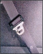
Belt System and Components
Next perform a visual check of the belt system. Does the webbing look as though the belt is frequently worn? Are the edges of the selvage frayed from the guide loop? This may be less helpful when inspecting newer vehicles. Are the seat belts or buckles visible? Has either been pushed underneath the seat? Remember, paramedics could have been in the car and moved these components during the rescue efforts. These general observations are not conclusive but will serve to bolster or contradict conclusions that may be drawn later.
Visually inspect the webbing. Are there stains or markings that would not be there had the belt been spooled up? Note locations of blood stains, dirt, glass fragments, etc. Are the stains a post-collision occurrence? A paper clip or marking pen may be useful in denoting points of physical evidence.
If your examination occurs within a few days of the event you should feel the belt. If the belt was significantly loaded (Delta-v is more than 12 mph or so) it will feel stiff. The higher the delta v, the stiffer the feel. Compare the way the webbing feels with the other belts in the vehicle. Unloaded belts will feel pliable. Continued manipulation of the stiffened webbing may increase the pliability of the belt material. Wear only latex gloves for this type of examination, as leather does not afford enough sensitivity to the touch. Again the history of this belt is important. Make sure the webbing has not been used to cinch closed doors of the car, or has not been excessively weathered. These effects will also produce a stiff feel. Consider also that the belt may be dried out due to exposure to natural elements.
Look for shiny surfaces on the webbing, these can indicate either material abraded or melted off of the latch plate guide ring, or skin from an occupant which may also be abraded and gives a similar shiny appearance to the webbing.
Some experts use a cellophane type strip, the length of the webbing (or in sections) to copy items of interest from the webbing. Look for areas of waviness or curling. These buckles (or puckering) tend to indicate tensile forces (loading). Close examination of the stitching with a magnifying glass may show a change in the pattern of the weave, as may burst stitches in higher delta v events. Go to the area of the load limiter and also examine that area closely for similar effects.
Recall at the beginning we observed the effect of a collision force on the vehicle was determined by F = ma. This relationship also applies to occupants and restraints. The more mass contained by the occupant, the greater the force that person is going to impart on the restraint system, and by Newton's 3rd law, receive an equal and opposite force from the seat belt. Therefore, the larger the occupant the more likely force related anomalies such as puckering or stiffening will be seen if the system was being used.

Examine the latch plate guide loop (D-ring) at the rear inner portion by pulling the webbing forward. Look for abrasions of the material or small strips of plastic that have been melted in appearance. The rapid pay out of webbing can generate a great deal of frictional heat to abrade and melt the plastic ring. Cloth material may be present in this location as the webbing pulled some fabric from the occupant with it. Look for cracks or bends indicating extreme loading or brittle material.
Metal guide rings show virtually no evidence of abrading or melting. Some metal guide rings have plastic teeth with an appearance similar to a multiple diamond pattern. These are also difficult to examine for trace evidence.
Inspect the end of the webbing near the anchor point. Many belts will have tags sewn on them to indicate the manufacture and date of the belt. Newer models, however, have this data painted on not sewn on with a label. If the label is present, look at the stitching to see if it is pulled, broken or puckered.
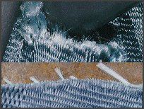
Cuts or lacerations in the belt are very common in events where rescue personnel have had to remove the occupant. These cuts are fairly easy to distinguish due to the clean appearance and straight cut edge of the webbing. An irregular, uneven, feathery, or horse tail appearance is more consistent with a burst failure of the webbing. These are rather uncommon but do occur. The horsetail appearance is most apparent in the nylon webbing, where the feathered appearance is more common in the polyester webbing.
Next, examine the webbing in the area of the latch plate guide ring. Many belts will show a historical location of the guide ring placement by an accumulation of grit and a fold pattern at the site. Examine the latch plate. Does the plate show sign of wear, or signs of uncommon wear? Look at the latch hole. Does it appear to be scratched up showing frequent use? Does the hole appear distorted, brinelled or gouged? These anomalies may be present in extreme load cases.
Gently pull on the webbing to see if the retractor is locked up or hung up on some component. See if the webbing pays out and spools up smoothly or if it is hung up. Occasionally, belts will become folded near the retractor or shoulder guide ring preventing them from spooling in completely. In these cases the occupants were not afforded full protection from the restraint due to this additional, unnecessary webbing slack.
Slip the latch plate into the buckle. Listen for it to seat with a "click." Did it seat easily? Tug on the latch plate to see if it comes out of the buckle. Wiggle the tongue to see if it stays firmly seated. Apply pressure to the release button. Does it require a firm pressure? Does it release the tongue smoothly? Push the release button and get a feel for how well it works. Does the button rebound to its upper position and remain there?
The attachment points should be inspected also. If the floor is carpeted over and the attachment underneath, inspection of the attachment from above is difficult without cutting the carpet. The area about the attachment should be inspected for bending and buckling. Check the rocker panel and B pillar attachment points to the car. A 30-mph delta v can cause in excess of 1,000 lbf of loading at these points and some deformation of the surrounding metal may be evident for higher speed collisions.
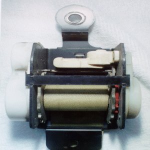
For higher speed change collisions if examination of the retractor mechanism is demanded, the retractor may need to be unbolted and removed. Make sure to examine any bolt and the surrounding metal for stress or deformation prior to attacking the removal of the component. Also, in higher speed change collisions, check and mark the location of the ratchet teeth and the belt on the spool. This may involve counting revolutions, or marking the belt as the retractor assembly is removed from the vehicle.
Examine the teeth of the ratchet and the locking bar or pawl to check for signs of local deformation consistent with their having struck each other. This is frequently observed in speed changes of more than 30 mph. Typically the ratchet teeth are offset, when a higher load is applied and the pawl engages the teeth, two teeth (one on each side of the spool) should do so as opposed to one. The pawl should show corresponding signs of this contact.
Testing the Retractor
If the vehicle is equipped with a webbing sensitive retractor, a sharp tug, exceeding the 0.7 G acceleration, will activate the retractor. This type of sensing strategy has fallen into disfavor among manufacturers. The investigator is most likely to find these types of systems installed in older vehicles.
To test vehicle sensitive retractors, the investigator may have to put the vehicle in motion. At a speed above 5 mph, brake aggressively and tug on the torso webbing sharply. The vehicle sensitive retractors should lock. If the vehicle is not driveable the retractor may be tested by loading it securely on a flat-bed tow truck and performing a similar test as above.
|
Some vehicle sensitive retractors may be tested with a combination sharp tug on the webbing accompanied with a blow from a rubber hammer in the area of the retractor mount. In these cases do not actually strike the retractor. Strike an area nearby. Successfully locking of the retractor using this technique is good evidence the retractor is operating properly. Failure to lock the retractor in this manner does not indicate the retractor is faulty. Rather the investigator should try one of the other techniques suggested. Some authors have suggested tipping the vehicle on its nose. This employs a large enough component of gravity, acting on the inertial device in the retractor, so that the pendulum is forced to perform. You may then test the restraint system by giving the webbing a sharp tug. Getting to the belt under such conditions may be a task in and of itself. However, lifting the vehicle from the rear via a tow truck may be the most convenient way to accomplish this task. |
Measure and document the distances from the forward portion of the seat bottom to the underside of the dash. In particular, measure the distances to impact sites on this portion of the vehicle interior. Measure distances from the seat back or headrest to contact strikes on the steering wheel, windshield or upper areas of the dash. Measure the distance from the seat back or headrest to the steering wheel hub. If the steering wheel hub is bent, look for evidence of contact beyond the steering wheel. Steering wheels that appear bent after the collision were bent well beyond their post collision relaxed location. Did it strike something behind it?
Though impact loading by the driver may compress the energy absorbing steering columns, often during heavy rescues, the jaws-of- life will be used to force the collapsed steering wheel away from a trapped occupant. This may give the mistaken appearance of excessive interaction with the steering wheel and column. Lipstick, tooth marks and other similar injury patterns can assist in determining not only excursions, but rotational motion of the upper body.
Measure the lengths of the belts using a fixed point such as an anchor, webbing sleeve or latch plate as a known starting point and locate items of interest and evidence in a belt based coordinate system. Cuts in the webbing, stains, wear from the latch plate location, curling, etc. should be collected. The length of the belt in use may be determined in this manner. Through the use of an exemplar model, or the occupant themselves, the distance between the body parts and the impact sites they struck may be measured. These measurements can be used to determine if the occupant was either too close for the system to function properly, not restrained or improperly restrained, system failure, or the speed change was beyond the capability of the system.
When inspecting passive/active systems such as manual lap belts with automatic shoulder belts, use great care. One or the other, or neither restraint may have been in use. Examine each portion separately and carefully. Excursions may assist in determining whether a portion the restraint was worn.
Slip Pawl
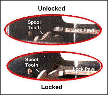
Slip pawl or skip lock is a fairly recent complaint. Often the source for this claim that the occupant had a more severe interaction with the interior structures of the vehicle than would be expected from the magnitude of the collision. Slip pawl allegedly occurs when the pawl fails to engage or to remain engaged with the initial ratchet tooth. Instead it "slips" across several teeth until becoming engaged and locking. Removal and disassembly of the retractor housing are necessary followed by a microscopic examination. Indications of such an event would be evidence of engagement of several of the teeth of the ratchet, and the wear pattern on the tips of the teeth. Some authors claim that "slip pawl" does not commonly occurr. Rather, evidence interperted as "slip pawl" is just normal retractor wear.
If you confront this issue you in your investigation, be sure to remove and examine retractors from both sides of the vehicle. This will supply a potential standard for comparison.
Conclusion
Seatbelts perform a very simple job. They apply vehicle accelerations to occupants through parts of the body most capable of accepting those forces. When examining a collision vehicle we attempt to determine what applied these forces to the occupant. Was it a collision with the interior of the vehicle, or was it a collision with the restraint system.
Conclusions about whether or not belts were worn depend in large part on the severity of the collision. It is highly improbable that low Delta-v collisions will provide evidence sufficient to support a conclusion. On the other hand collisions involving large delta-vs offer many clues that can lead the trained investigator to a conclusion. Most collisions at issue fit between these extremes and may require expertise in other disciplines.
The investigator is encouraged to collect his evidence purposefully. Weigh the evidence carefully, and recognize that "no conclusion" is a possible answer to the question posed.
Sources:
SAE TOPTECH - Passive Restraints
SAE 840396 - Diagnosis of Seat Belt Usage in Accidents.
SAE 840392 - Historical Perspective on Seat Belt Restraint Systems
NHTSA - FMVSS 208, 209, 210
Texas A & M - Biomechanics Course
Biomechanics of Trauma, by Nahum and Melvin
CHP Academy - lecture notes from TAR
The position provides on-scene documentation through total station survey and photography of traffic collisions involving severe injuries and death. The entire County population is over 3 million residents, and the County maintains over 1,800 miles of roadways. Mr. Phillips has investigated hundreds of fatal collisions during his time with the County. He is used as a consultant for allied agencies, County Counsel and the District Attorneys' Office.
Mr. Phillips has consulted with Law Firms through out the western United States as well as the State Attorney Generals Office and the Department of Transportation.
Mr. Phillips holds Bachelor Degrees in Criminal Justice and Engineering (Manufacturing) and has attended many hundreds of hours of specific technical training in the field of collision reconstruction.
He can be contacted at Edphill@home.com
|
Copyright ©
|