
The Traffic Accident Reconstruction Origin -Article-


The Traffic Accident Reconstruction Origin -Article-
|

|
by Bruno Schmidt, Ph.D.
Introduction
Many accident reconstructionists assume that a braking automobile has approximately 60% of its weight supported by the front tires, and 40% by the back tires[1]. If, then, there is evidence that only the front tires are not rotating (either because of faulty rear brakes or if collision damage has pinned only the front wheels), the effective drag factor is taken as 60% times the coefficient of friction (assuming a level roadway), while in fact, the actual value depends on the height of the center of gravity, the location of the center of gravity between the front and rear tires, and the coefficient of friction. Vehicles with a high center of gravity or with a large weight distribution at the front (as with many front-wheel drive cars) can depart significantly from the 60-40 rule.
Another analysis[2] assigns 70% loading to the front wheels for a vehicle that has 50% loading in the static case, which may be an overestimate. In [2], this 70% loading is applied to an example where a second car, with all wheels sliding, moves with the first as one unit. The added drag of the second car reduces the effect of the 70% loading on the first car, which can lead the reader to believe that different loading on the front tires of a single vehicle doesn't make much difference, even though an exact derivation is found in this reference[3].
A third analysis[4] gives the loading shift for changing decelerations of a single car with a static weight distribution of 52-48 (front-back). This treatment does incorporate the various factors mentioned above. It does not, however, calculate the effective drag factor with changing loading, so it is of limited value to the accident reconstructionist unless additional calculations are done.
The purpose of this present paper is to apply laws of physics to a braking vehicle to determine the actual weight distribution, and to examine the validity of the 60-40 rule for a number of actual vehicles. The results will be displayed in a format that can readily be used by a reconstructionist without a lot of extra work. An alternate derivation can be found in the literature[5].
Theoretical Analysis
For a level roadway, a braking vehicle experiences only a horizontal acceleration. Therefore, according to Newton's laws of motion, the sum of the vertical forces acting on the vehicle must be zero. The vertical forces on an automobile are the normal forces of the roadway pushing up on the tires to counteract the effect of gravity pulling down. Gravity effectively acts at the vehicle's center of gravity (CG). The two normal forces, gravity, and the braking forces, along with the horizontal braking forces of the roadway on the tires, are displayed in Figure 1.


Data that are required to calculate FRONT and REAR can be found for a number of vehicles in the May/June 1989 issue of Accident Reconstruction Journal[6]. Some of that data have been used in the accompanying tables. Several different values of f1 and f2 have then been used to determine the results for FRONT and REAR from the equations above. Those entries with f2=0 correspond to the rear wheels being free-wheeling. Table 1 is for numerous automobiles; Table 2 is for several light trucks and vans.
In examining the tables, it should be pointed out that the column heading b2/Bx100% represents the percentage of the weight that is supported by the front tires under static conditions, i.e., no braking. The column heading FRONT % shows the percentage of the weight that is supported by the front tires when braking occurs. The numbers in that column should be multiplied by the coefficient of friction to obtain the effective drag factor for purposes of calculating skid-to-stop speeds. For example, if a drag sled (or a vehicle with all brakes functioning properly) were used to measure the coefficient of friction and gave a value of 0.85, then a 1986 Buick Skylark with front wheel braking only should have the 0.85 coefficient of friction multiplied by 0.777 in using the skid-to-stop speed formula, since 77.7% of its weight is supported by the front tires. This yields a value for the speed that is significantly higher than what would be obtained by using a multiplier of 0.60 that is traditionally used--in fact, the correctly calculated speed is 14% higher!
By studying just those entries for front wheel braking only with a coefficient of friction of 0.85, it can be seen that all of the front wheel weights are at least 19 percentage points higher than the static values. For vehicles not listed in the tables, calculation of the exact value requires a knowledge of both h/B and b2/B. Usually it is not difficult to obtain b2/B from various sources, but h/B can be harder to come by. It appears that a conservative value for the front weight distribution during braking can be calculated by adding 19 percentage points to the percentage of the weight supported by the front tires at rest. For a drag factor of 0.60, it appears that 13 percentage points could be added to obtain a conservative estimate. Another approach is to use a value of h that is 40% of the total vehicle height[7].
If both front and rear brakes are working, the weight shift to the front tires is even greater. This is because there is more braking force producing more torque that tries to make the vehicle rotate counterclockwise. The front tires, which produce the only clockwise torque, must push up with a greater force to prevent that rotation from taking place. For purposes of calculating speeds from skid formulas, however, this greater weight shift doesn't matter. Between the front and the rear tires, the full weight of the vehicle is being supported, and since both front and rear tires are braking, the full drag factor can be used regardless of the weight distribution.
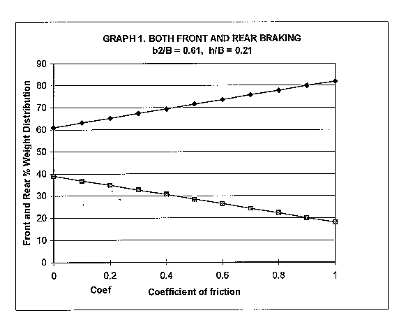
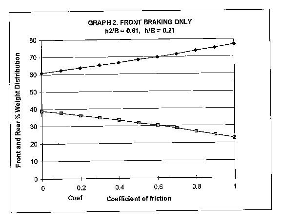
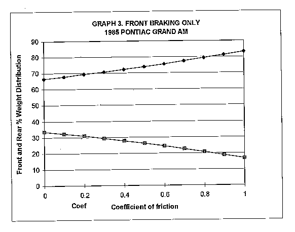
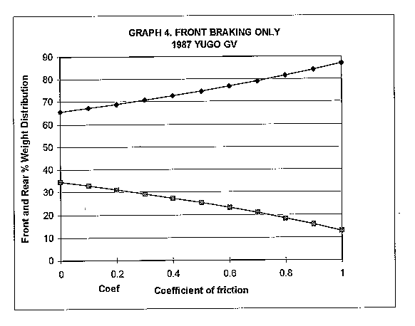
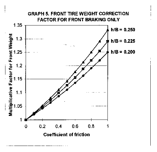
Graph 1 displays the weight shift for increasing coefficients of friction for a typical automobile, using average values from Table 1, assuming all four wheels are locked. Behavior for the same typical automobile with only front wheel braking is displayed in Graph 2. Graphs 3 and 4 show front wheel braking behavior for the two most extreme automobiles in Table 1. Graph 3 is for the 1985 Pontiac Grand Am, which has the highest concentration of weight on its front tires under static conditions. Graph 4 is for the 1987 Yugo, which has the highest center of gravity.
General Application
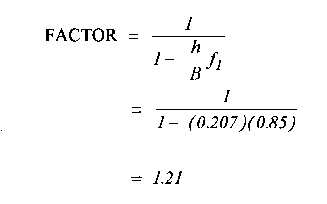
Since the above examples address only a limited number of vehicles, it would be useful to develop techniques for a more general application of the results. This can be done if one limits the analysis to the weight shift with front wheel braking only. In this case, f2 = 0, and the front weight percentage simplifies to


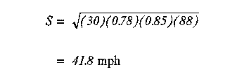
As an example of using this factor, assume that a 1988 Nissan Maxima has its front wheels locked after a collision, and travels 88 feet on a roadway with coefficient of friction 0.85 before coming to rest. What was its speed immediately after impact? If one uses the 60% rule, the result is:



References
1. Westmoreland, R., Advanced Accident Investigation Course, Texas A&M, June, 1992.
2. Fricke, L., "Traffic Accident Reconstruction," Volume 2 of The Traffic Accident Investigation Manual, Northwestern University Traffic Institute, 1990, pp. 62-28 and 62-29.
3. Fricke, L. "Traffic Accident Reconstruction," Volume 2 of The Traffic Accident Investigation Manual, Northwestern University Traffic Institute, 1990, pp. 90-26 to 90-28.
4. Lueck, F. Gartland, W, and Denholm, M., "Proportional Valve to Skid Control--A Logical Progression," SAE Paper No. 690456, May 1969.
5. Limpert, R., Motor Vehicle Accident Reconstruction and Cause Analysis, Fourth Edition, The Michie Company, pp. 437-441.
6. Garrott, W., Chrstos, J., and Monk, M., "Vehicle Inertial Parameters," Accident Reconstruction Journal, Volume 1, No. 3, May/June 1989, pp. 22-29.
7. 4NX6PRT Systems, Expert Autostats, 1991, p. 19.
Dr. Bruno Schmidt received his Bachelor's degree in mathematics and physics from Cornell College in 1964. His Doctorate degree in physics followed from Iowa State University in 1969.
Dr. Schmidt was a Physics faculty member at Southwest Missouri State University (1969-1984) and head of the Computer Science Department at Southwest Missouri State University (1984-1992). Currently he is Vice President for Academic Affairs at Southwest Missouri State University.
Dr Schmidt has been practicing in the field of accident reconstruction since 1989. He also teaches the Applied Physics for Accident Reconstruction for Texas A&M Engineering Extension Service.
He maintains active memberships in Texas Association of Accident Reconstruction Specialists (TAARS) and National Association of Professional Accident Reconstruction Specialists (NAPARS).
He can be reached at SchmidtBF@aol.com
|
Copyright ©
|